From A to Z: Distilling FE Analysis into the Z-Matrix for Comprehensive Magnetics Design
A. Vital, A. Delgado · IEEE Applied Power Electronics Conference (APEC 2027), New Orleans, LA · 7–11 March 2027

Free academic software · Universidad Politécnica de Madrid
MAGNETISiM runs the finite-element solver for you (FEMM today, Elmer next) and extracts the impedance matrix of every winding across frequency. From that one result it answers the rest: inductance and leakage, winding and core losses for any excitation, any series or parallel connection of windings, and a passive SPICE model. No new simulation needed.
Data providers & collaborators


Fast simulation, fast prototyping
What you enter is drawn, simulated and post-processed for you.
Pick a catalog core (TDK, Ferroxcube, Micrometals…) or enter your own dimensions. The 2D and 3D views follow as you type.
Round, Litz or PCB conductors, layer by layer, with insulation and coating.
Frequency sweeps or waveforms with harmonics. FEMM runs in the background while you keep working.
Impedance matrices, winding and core losses, capacitances and a passive SPICE model.
PCB layout and manufacturing files, straight from the design.
PCBSiM · in development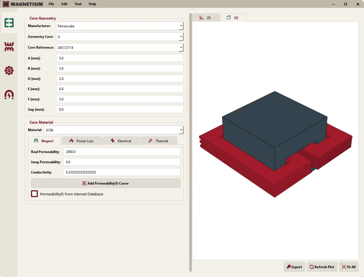
One design feeds every tool, so the numbers stay consistent from one to the next.

Magnetic field · available
Frequency-dependent impedance matrix of every winding, with skin and proximity effects and core losses.

Electric field · available
Electrostatic analysis of the same geometry to obtain the parasitic capacitances between windings and to the core.

Circuit models · available
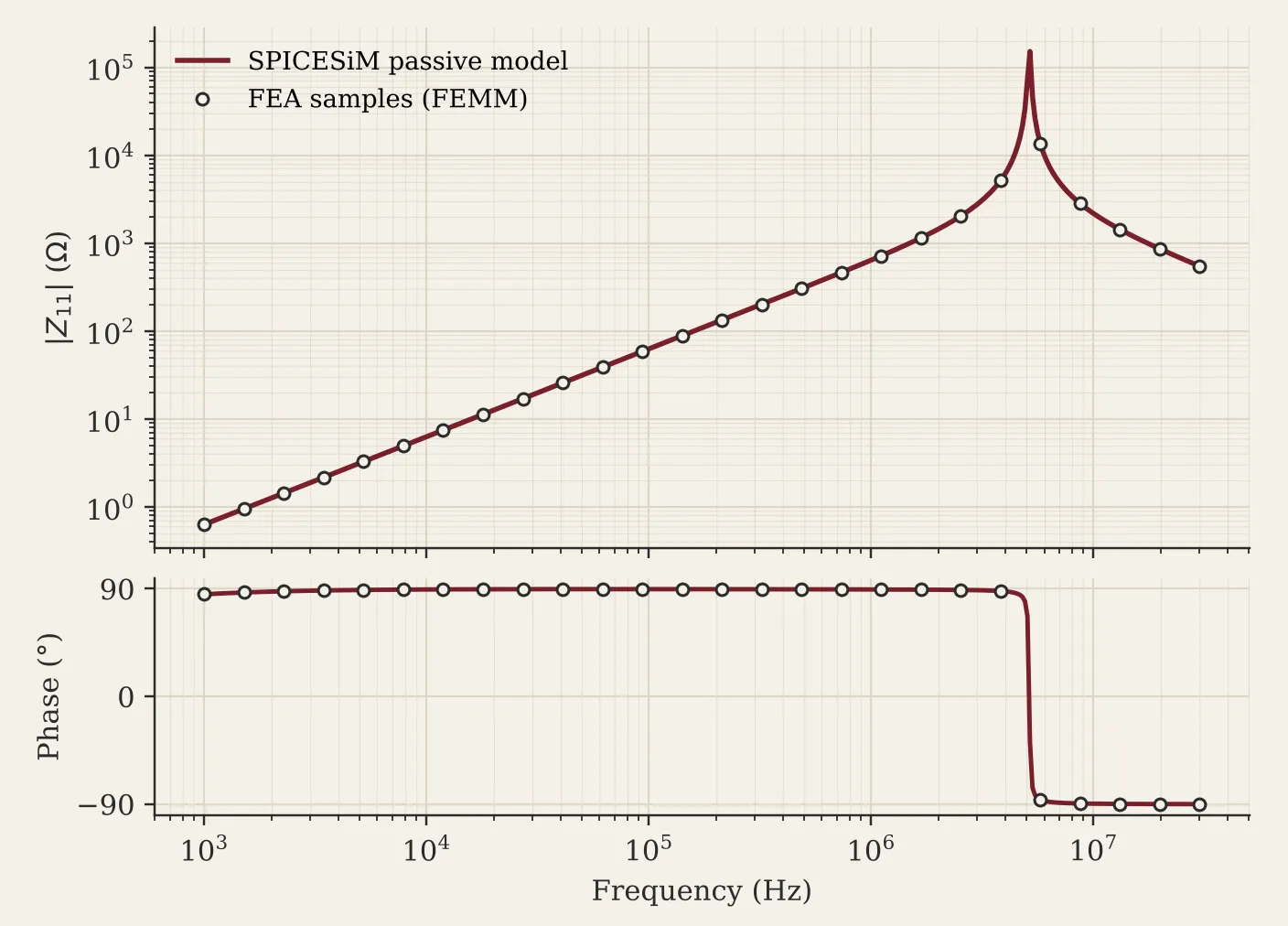
Vector Fitting turns the simulated matrices into a passive state-space model you can drop into a converter simulation.
In development

Enter your converter and its specifications and get construction options to take into MAGNETISiM.

PCB layout and manufacturing files, straight from the design.

Temperature rise from the computed losses, with Elmer.
2D speed, 3D cores
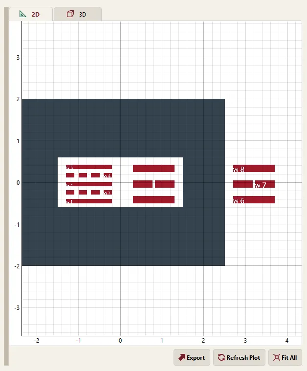
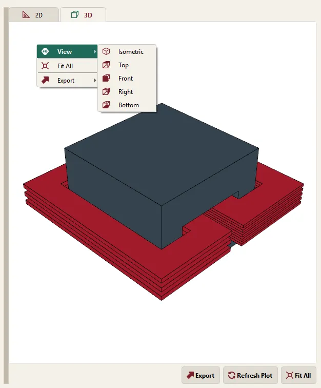
Commercial 3D cores are mapped onto equivalent RZ or XY models that keep the reluctance of the real core, so a full frequency sweep stays a 2D problem. The 3D view shows what you are actually building.
From field to circuit
SPICESiM fits the simulated impedance matrix with Vector Fitting, searches the lowest order that meets your error target and corrects the model so it stays passive. The result is a netlist and a symbol, ready for your circuit simulator.
Order search · passivity enforcement · reciprocity option
Post-processing
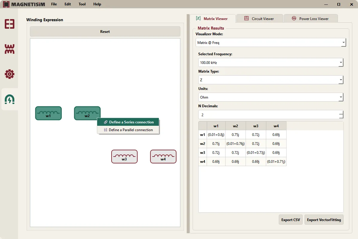
Connect windings in series or in parallel after the run and read the resulting matrices, circuit quantities and power loss at every simulated frequency.
What we are building next. No dates yet.
Full 3D finite-element models for the cases a 2D model cannot capture.
From losses to temperature rise, in the same design.
EXPERTISiM proposes how to build the component; MAGNETISiM tells you how it will really behave.
PCBSiM turns the winding into a board you can manufacture.
MAGNETISiM grows out of esaFEMM, developed at UPM in collaboration with the European Space Agency.
All publications →From A to Z: Distilling FE Analysis into the Z-Matrix for Comprehensive Magnetics Design
A. Vital, A. Delgado · IEEE Applied Power Electronics Conference (APEC 2027), New Orleans, LA · 7–11 March 2027
Core and Winding Modeling in MAGNETISiM: a Platform For Fast Prototyping of Magnetic Components
A. Vital, A. Delgado · 14th European Space Power Conference (ESPC 2026), Estoril, Portugal
Platform for Fast and Easy Simulation and Modeling of Magnetic Components
A. Vital · 1st Annual Meeting of the CEIMM (2026)
Bachelor’s, Master’s and PhD projects that end up in a tool people use.
Join the team →Collaborations go through formal agreements with the Universidad Politécnica de Madrid.
Become a sponsor →Open an issue on GitHub or write to us. It helps us decide what comes next.
Report a bug →